RF Sputtering provides several advantages:
- It works well with insulating targets
- The sign of the electrical field at every surface inside the plasma chamber is changing with the driving RF frequency. This avoids charge-up effects and reduces arcing.
- RF Diode sputtering technology, recently developed works even better, because it does not need magnetic confinement and provides optimum coating uniformity. It provides a very flat target erosion with no racetrack, no poisoning of the target, little or no arching and a more stable process. This requires a very well designed matching network and components.
- There are no disappearing anode problems
For conductive coating target materials (metals), mostly DC sputtering is used where the gas discharge is produced by a direct current (DC) power supply. Ions from the gas discharge are accelerated to the target surface, where their impact energy breaks out target material atoms from the target surface generating a target material vapor that forms the coating on the substrate.
To generate non-conducting coatings, often the DC reactive process is used with a metallic target and some reactive gas applied to the plasma where the final insulating coating material is generated by a chemical reaction between target material and reactive gases.
But there are some strong limitations of the DC sputtering process if a insulating coating is deposited or the substrate is an insulator:
- A insulating target can not be used. In this case, the target will block the DC current and no stable gas discharge can be produced.
- If the substrate is insulating, there is a charge up of electrons, which frequently generates arcs.
- If an insulating coating is deposited by a DC reactive process, the growing insulating film on the substrate and anode area is charged up which then generates arcs.
Furthermore, the anode is coated and slowly turns into an insulator over time and creates the disappearing anode effect, which causes even more problems.
There are several processes available that attempt to reduce arcing by pulsed DC supplies and to avoid the disappearing anode by a dual cathode balanced magnetron configuration.
All industrial DC sputtering applications used today, are designed with magnetic plasma confinement by magnetron cathodes, which improves sputtering rate and reduces the electrical resistance of the plasma to values between 10 W and 100 W.
There are several major shortcomings with regards to using magnetron cathodes for these specific applications.
First, they generate a much worse uniformity compared to cathodes without magnetic confinement and the high resistance of the DC cathode (~kW) needs DC supplies with high voltage capabilities, which are not covered, by standard DC plasma supplies.
Secondly, magnetron cathodes work worse or not at all if magnetic target materials are used due to the magnetic shortcut generated by the target that drastically reduces the plasma confinement.
We have several new unique solutions for the aforementioned problems associated with DC sputtering of insulators or magnetic materials via unique RF sputtering processes that have been developed for these challenging applications.
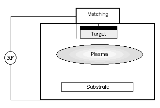
The general configuration is shown in Fig. 1
Figure 1: RF Sputtering Configuration
For RF sputtering, a high-frequency generator is used generating electromagnetic power in the MHz-Region (typical: 13.56 MHz). The output voltage and current capabilities of these generators are limited, so they need to work on a defined load impedance of 50 W.
The plasma impedance is normally different from this, so a matching network is connected to the cathode to transform the cathode impedance to 50 W needed by the generator.
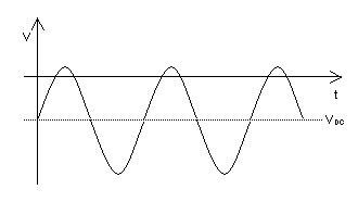
When the alternating signal is applied to the cathode, generating plasma, then the plasma acts as a rectifier that generates an average negative voltage at the smaller of both electrodes, which is in general the target. This negative voltage is called the self-bias or VDC voltage of an RF cathode. Fig. 2 shows the time-behavior of an RF cathode voltage.
Figure 2: RF Voltage At Cathode
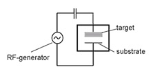
To build up a DC self-bias voltage, the cathode must be capacitively blocked to avoid dc currents. In principle, an insulating target itself works as a capacitor, but in most matching units a dedicated blocking capacitor is added to allow RF operation with conducting target materials, as well.
Due to the different masses, electrons can be accelerated to oscillate with the RF, while ions are to heavy and react only on the averages generated in the RF system.
The electron movement delivers a short current pulse when the cathode is positive and a smaller current longer pulse time when the cathode is negative resulting in a zero current average.
The ions are only affected by the self-bias voltage VDC that accelerates them to the target and approaches the equivalent voltage applied during DC sputtering.
RF Sputtering provides several advantages:
- It works well with insulating targets
- The sign of the electrical field at every surface inside the plasma chamber is changing with the driving rf frequency. This avoids charge-up effects and reduces arcing.
- RF Diode sputtering technology, newly developed updated on an old technology works even better, because it does not need magnetic confinement and provides optimum coating uniformity. It provides a very flat target erosion with no racetrack, no poisoning of the target, little or no arching and a more stable process. This requires a very well designed matching network.
- There are no disappearing anode problems.

rf_diag1

rf_diag2

RF Sputtering
- 0
- 1
- 2
